N64 RGB Mod

N64 RGB Mod (With DIY 7316 Amp)

While the N64 was not outfitted with RGB capabilities from the factory, it does have RGB pins present on the multi-out connector on the back, and it also has RGB in-use within the console itself.

What this means is; all we need to do is run the RGB lines from within the console, over to the multi-out, and amplify them. This will achieve a great quality RGB signal for use on a PVM/BVM or SCART capable retro gaming setup.

"S-Video is supported out of the box for N64 with a suitable cable"

S-Video is supported out of the box for N64 with a suitable cable that can be had for a few bucks, and I would recommend you use it, unless you have a specific reason to use RGB. The quality difference between the two is neglegible at best. For my use, I want all my consoles to be either SCART or Component video capable, for use with an Extron Matrix switch to keep my setup as easy as possible to have everything hooked up and ready to use at a moment's notice.

Texas Instruments 7316 Video Amplifier

You may be asking at this point, why bother creating your own circuit, when alternative ready-made solutions exist, like the excellent N64 PCB from Voultar?

Firstly, this solution is much cheaper. You can purchase the THS7316 for about $0.25 each on ebay, and the little PCB that you solder it to is about $0.99 for 20pcs. If you have the tools and some spare resistors and capacitors around, this mod can be done for next to nothing! The only downside here, is that they’re not usually sold in singles, so you may have to buy 5 or 10 of each.

Secondly, the reward of doing something that can be a little challenging for yourself. It’s fun to tinker with mods, and taking on a project like this is a great way to hone your skills as a modder and tinkerer. Since you’ll likely be buying more than one of the small parts, you can mess it up a bit and it will only cost you pennies.

THS 7316

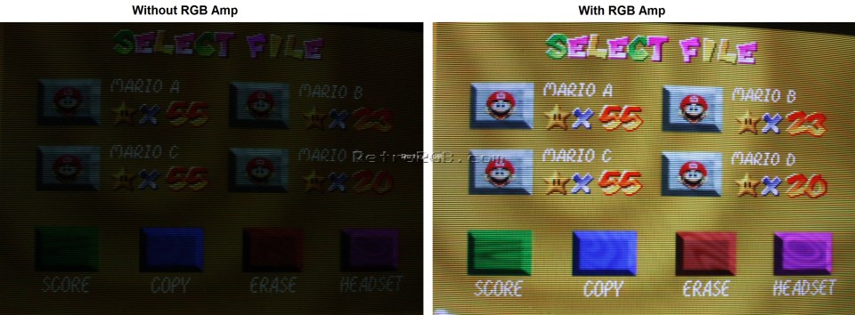
The THS7316 is a very simple video amplifier with RGB input pins on one side, and RGB output pins on the other. The two remaining pins are for ground, and +5V power. It’s needed in this project because the RGB signal from the N64 alone is not powerful enough to drive a proper output to your TV, resulting in an extremely dark image, as shown below.

Credit: RetroRGB.com N64 DIY RGB

Prerequistes To Consider

Before jumping in and purchasing parts, please make sure your N64 is compatible with the style of mod we’re doing today. In North America, you can look for a serial number on your console that starts with NS1. It’s also a good idea to open it up and be sure, by locating the video chip that includes the RGB signals we’ll be tapping into. The chip is a VDC-NUS or VDC-NUS-A. For more information on the available options with different N64 systems, please visit the RetroRGB page on this subject. You can also see a serial number guide here, that will give you a good idea if your console will work.

Parts List

Item Quantity
THS 7316 Amp 1
SOIC-8 to DIP-8 PCB 1
75 ohm Resistor 3
0.1uf Capacitor 1

Tool List

  • 4.5mm Line Head Screwdriver (AKA Gamebit Screwdriver)
  • Soldering Iron
  • Solder Flux
  • Solder
  • Wire (22AWG – 30AWG recommended)
  • Multimeter (for checking your work)
  • Shrink Tube
  • Lighter or Heat Gun
  • Flush Cutters
  • Kapton Tape or Electrical Tape or Double Sided Tape

Step 1: Dissasembly and VDC-NUS Check

Open up your console by removing the Expansion Pak/Jumper Pak on the top, and the 6 screws holding the case together with your 4.5mm Line Head Screwdriver.

If you look just above your cart slot, you can see a CPU designation. If your system is a NUS-CPU-01, 02, or 03, you should be good to go. If you’re still not 100% sure, remove all the heat sinks and shielding on the top of the motherboard and take a look for the VDC-NUS chip. There are 26 screws in total, so make sure you keep track of their locations!

Once you’ve got your system taken apart, remove the screws I’ve hilighted in the above image only, then you can remove the board and flip it over. Remove the bottom shielding to reveal the bottom of the mainboard PCB.

Step 2: Prepare Your THS7316 Amp Circuit

Let’s get your 7316 amp ready. Tin the leads on the amp, and the small PCB with some solder and flux, then solder them together. Make sure you align pin #4 of the 7316 to the square pad on the PCB. If you’re not experienced with this, you likely ordered more than one of each, so this is a great place to practice your skills. It’s easier than it looks, I promise!

Step 3: Finish The Circuit

Next, solder on the remainder of the components. Start with a length of wire about 5 inches in length. Strip, tin, and attach it to the ground, then do the same with the +5V. The 0.1uF capacitor will go from the +5V to the ground to eliminate inductance.

You can then attach the three 75 ohm resistors to the output side of the PCB, and snip the leads off. Save the leads though, we’re going to use them later. Attach some 5 inch wires to these as well.

Then, take some little pieces of heat shrink and cover up the bare sections so they don’t short out. I just used a lighter to do this, but a heat gun or hot air station will work too.

Step 4: Use Resistor Leads to attach to the N64 Board

On the N64 board, there are vias @ R10, R9, and R8. You can solder directly to these vias, eliminating the need to run wires around to the other side of the board to the VDC-NUS chip to get RGB to your circuit. Blue is R10, Green is R9, and Red is R8. When soldering the leads to the vias here, you need to make sure you only insert the leads as far as the thickness of the board or a bit less. If you insert them too far, they can short out on the chip on the other side of the board, and your mod won’t work!

Step 5: Attach Your Circuit

Take some kapton tape, double sided tape, or electrical tape and pierce it over the leads to create a nice barrier between the N64 board, and the little PCB you’re going to install, then insert it and solder it into place.

Then, you can snip off the leads for a nice clean look. I feel this is a great way to have a nice clean install, as well as a mounting spot for the board, all in one nice solution. If you’d prefer to run wires instead, that’s of course a viable option here.

Step 6: Attach Wires to the Multi-Out Pins

We now have only 5 wires to attach to the multi-out, then we’re ready to test it out! The diagram here shows the pinout of the Multi-Out connector on the bottom of the N64 board, and this is where you’ll be running your wires.


You can run them any way you like to make a neat looking install, but I have a photo of my install below so you can see how I did it.

Step 7: Test & Button It Up!

Now it’s time to test. Make sure you insert your expansion pak/jumper pak as well, or the system will not boot. If you’re happy with the mod, you’re done! Put it all back together and enjoy!

If you’re having troubles for some reason, the first place you should probably check is continuity to all the points that should be joined, to make sure your soldering is sound. After that, I would check to see if your leads are inserted too far in the vias for RGB.

Good luck!

Cables

There are a number of high quality SCART cables out there that you can use with this mod, so I won’t link them all. This is the one I used, however and I’m very happy with the results.

Thanks for reading.

I hope you enjoy what you find on my site, and I will do my best to keep the content flowing as long as I can. Please feel free to comment anywhere on the site, as I would love to hear from you.

– raskulous

Posted by

Raskulous is an avid gamer, retro gamer, and computer enthusiast. He also spends portions of his free time doing electronics service and repair, and console modifications.

Leave a Reply

Your email address will not be published.